use/less
As an Industrial Designer I live in a world of creation dictated by usefulness, sleekness, and functionality. However, I have always been fascinated by objects that at first seem useful but in the end show how incredibly useless they truly are. My journey into objects that are useless in not any easy one, my formal training and continued professional practice make it difficult for me to produce an object for the sake of that object. I challenged myself to take an object that most people can relate to and also understand the usefulness on first glance. Upon further inspection of the object, in this case a lamp, the user realizes the uselessness of the object.
I took visual inspiration from the concrete usage in Russian Architecture and contrasted it with copper, a material that exists in a dichotomic state being both cold and visually warm. So the bones of this object have come together to form something of interest slightly not square and imperfect in so many ways. The viewer is forced to reconcile the uneasy feeling of something that is seemingly unbalanced. The Lamp shade, angled back towards the base of the object puts a focus on the users hands as they interact with two metal protrusions from the base. These metal posts are points of interaction, no adjustability to the positioning of the light is offered, no ability to change the height the light, it is simply there.
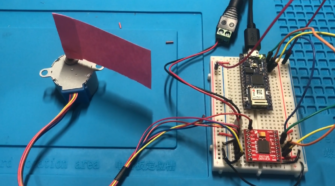
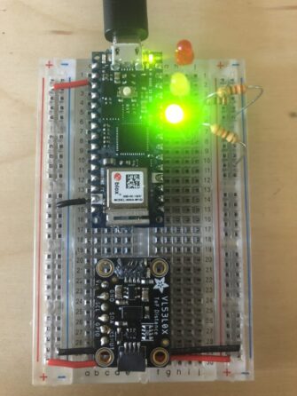
As I mentioned in my previous entry, my original intention was to use gesture control to change position of the lens as well as the brightness of the light. Below is the code that attempts to limit a stepper motor to have only 90 degrees of rotation. For some reason the stepCount variable would not update while using the APDS9960 gesture sensor. I gained two very important pieces of information from this lengthy process.
- Just because an interaction makes sense in your head does not mean it will be the most effective. After spending some time with a few different users I abandoned the use of the gesture sensor, It was mostly just frustrating. It was very unpredictable, it worked 100% of the time 10% of the time, in other words it didn’t really work at all. From miss-reading the gesture to not picking up the gesture at all, it just didn’t make sense to use it in this case. I think the sensor works OK sometimes however, to use it on a lamp makes it quirks really err…shine. Having the sensor placed anywhere that made sense for the operation of the lamp made its performance suffer even more.
- Don’t use a stepper motor when you really need a servo. Steppers are great for very precise movements, something I did not need in this situation. Steppers are also great for a device that needs continuous rotation, again I did not need continuous rotation I only needed 90 degrees. The use of the servo and a radial potentiometer really gives the user a connected feel to the movement of the lens.
Below is the code for using the gesture sensor to control the stepper.
#include "Stepper.h"
#include "Adafruit_APDS9960.h"
Adafruit_APDS9960 apds;

int stepCount = 0;
const int stepsPerRevolution = 1026;  // change this to fit the number of steps per revolution
// for your motor

// initialize the stepper library on pins 8 through 11:
Stepper myStepper(stepsPerRevolution, 9, 10, 11, 12);

void setup() {
  // set the speed at 60 rpm:
  myStepper.setSpeed(10);
  // initialize the serial port:
  Serial.begin(9600);

  if (!apds.begin()) {
    Serial.println("failed to initialize device! Please check your wiring.");
  }
  else Serial.println("Device initialized!");

  //gesture mode will be entered once proximity mode senses something close
  apds.enableProximity(true);
  apds.enableGesture(true);
}

void loop() {
  // step one revolution  in one direction:
  //  uint8_t gesture = apds.readGesture();
  if (stepCount < 510) {
    uint8_t gesture = apds.readGesture();
    if (gesture == APDS9960_DOWN) myStepper.step(51);
    stepCount = stepCount + 51;
    delay(100);

    if (gesture == APDS9960_UP) myStepper.step(-51);
    stepCount = stepCount - 51;
    delay(100);


    //  if (gesture == APDS9960_LEFT) myStepper.step(513);
    //  if (gesture == APDS9960_RIGHT) myStepper.step(-513);
    Serial.print("stepCount:");
    Serial.println(stepCount);
  }

}
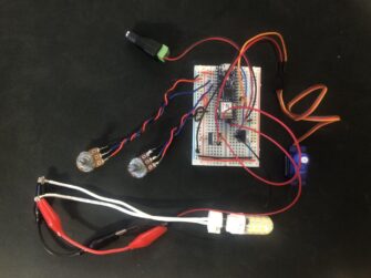
Conceptually the idea is to have a lamp that really only functions as an interaction with the lamp. Basically a useless lamp. Brightness is controlled via a rotary potentiometer placed on the left-hand side of the base and the lens position is controlled by a rotary potentiometer placed on the right-hand side of the base. There is a bit of discovery involved as the pots are not labeled on purpose. At this point you might be asking yourself “Why would I want/need to control the position of the lens?” Well ,my friend, I’ll tell you. This particular lamp has not one but two lenses, each lens is a composite of a lenticular array and a linear polarizing filter. The idea was to change the relative position of the lenses to change the light quality. What I basically ended up doing, not on propose I might add, was creating a variable detraction grating. This was not my intended outcome however, my goal was to change the quality of the light by rotating two lenses in relation to each other. In that sense I was fully successful in that goal.
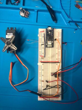
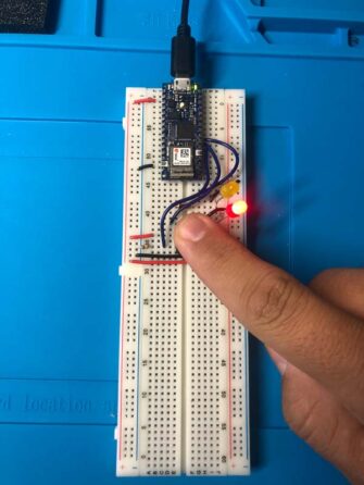
so now lets look at the code I used for the final implementation, two variables allow the position of the lens and the brightness to be adjusted independently of each other.
#include <Servo.h>

Servo servoMotor;
int servoPin = 3;
const int lampPin = 9;

void setup() {
  Serial.begin(9600);
  pinMode(lampPin, OUTPUT);
  servoMotor.attach(servoPin);
}

void loop() {
//  Lamp Operation
 int sensorValue = analogRead(A0);
   int outputValue = map(sensorValue, 0, 1023, 50, 255);
   analogWrite(lampPin, outputValue); //Adjust Lamp Brightness
   Serial.println(outputValue);

//Servo Operation
  int analogValue = analogRead(A1);
  int servoAngle = map(analogValue, 0, 1023, 0, 95);
if (millis()% 20 <2) {
  servoMotor.write(servoAngle);//Change Postion of Servo

}
Serial.println(servoAngle);
}
Fabrication of the lamp was not without challenge either. Aesthetically I wanted it to have an almost unfished industrial quality to it. Make the user feel a little uneasy while using it and also question why it was made. Unsealed concrete and raw copper tube were the materials I chose. They compliment each other well, over time and with continued usage both materials will gain a patina. The copper will patina fairly uniformly but the concrete on there other and will really only change in the places the user touches it. This will provide future users with more clarity of where the interaction points are but also speak to the object having some kind of history.

The physical object was basically one big problem solving endeavor. Casting concrete is fairly easy, but with a limited time frame and realizing this piece is a one-off it didn’t really make sense to make silicone molds of parts created just for this.
I used “flex-cones” as the mold for the lamp head. The voids would give some interesting detail to the form. But, and this is a big but, voids mean holes which means I couldn’t pour a liquid into it. So I used packing tape to create a shell over the cone. This covered the voids as well as gave some added rigidity to the mold. I also need a way to keep the inner cone and outer cone separated so the concrete could be poured into it. I unfortunately forgot to take pictures of this step. I used a hollow threaded rod at top of the cones to keep them separate. This also gave me a whole at the top of the lamp head in which I was able to pass the wiring though.


The base of the lamp was created in a similar fashion. A 2.5QT bucket was used for the base with three pipes used to create holes for the upright and the two potentiometers.

Again this was a two part mold to create a cavity in order to house the microcontroller and the potentiometers. This resulted in a very this slab where the upright would penetrate the base. Concrete can be very brittle when side load is placed on it. The slab was only about 0.25″ thick which would not support weight of the Lampe head. A second pour into part of the void created a slab that was thick enough to support the load placed on it from the lamp head.

I had to make extensions for the horn that I used. Brass tubing made quick work of this. The extension allowed me to place the servo behind the LED so as to no interrupt the light with the servo.

Final assembly was not a cake walk either. My hands are big, the inside of the lamp head is small, need I say more. Patients, tweezers, and some super sludgy metal (music) got me to a point where it all came together.


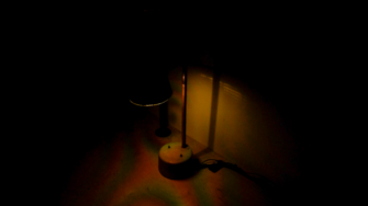
And Finally the lamp in all it’s uneasy glory.

There are so many changes I would make to this project, for one I would like to make this base 1’x1’x4′ so it basically sits on a pedestal. I would also want to make the able the head moor extrema to really show how useless it is. I wasn’t able to get this to run from wall power only. When the board was being powered from the wall, both the LED and the servo acted very erratically. The LED would go to full brightness at 50% through the potentiometer’s rotation and then fade back down in the other 50% of rotation. And the servo would not start to activate until about 30% through the rotation of the potentiometer and then would not actually turn, it would bounce back and forth between the starting position and about 10 degrees. I’m not sure why this behavior was being exhibited it could be because of a grounding issue or possibly power, but I don’t think it is power. I tested using 12V, 15V, and 16V all with about 3.5 amps. I tried to use a two 1000μF capacitors which didn’t really help at all. I keep the capacitor I used for the servo since it helped to clean up the output and removed some of the bounciness of the movement.
For the moist part I am fairly happy with the way this turned out. I set out to make a useless lamp that had two interactions brightness and light quality, both were achieved. As always I welcome feedback in the comments.
