A Tale of Two Inputs
Two types of inputs and two very different approaches to gather input form the physical world.
Two types of inputs and two very different approaches to gather input form the physical world.
Digital inputs are fairly straight forward for me, data can be broken down into 0’s or 1’s, some combination of these two integers will give the processor the information needed. Opening and closing a circuit in order to have some desired effect. Last week we looked at switches, I equate the digital input to a switch basically. In one state it sends a “1” and in the other state it sends a “0”. This can be used for many different types of actions. However, the real fun comes form the use of or addition of analog switches. In the video below a rotary potentiometer is used to adjust the brightness of an LED through changing the voltage, the rotary potentiometer is a variable resistor.
Now is when the everything falls apart breadboard √
Nano 33 √
Wiring √
LED’s √
Some analog inputs √
working IDE…
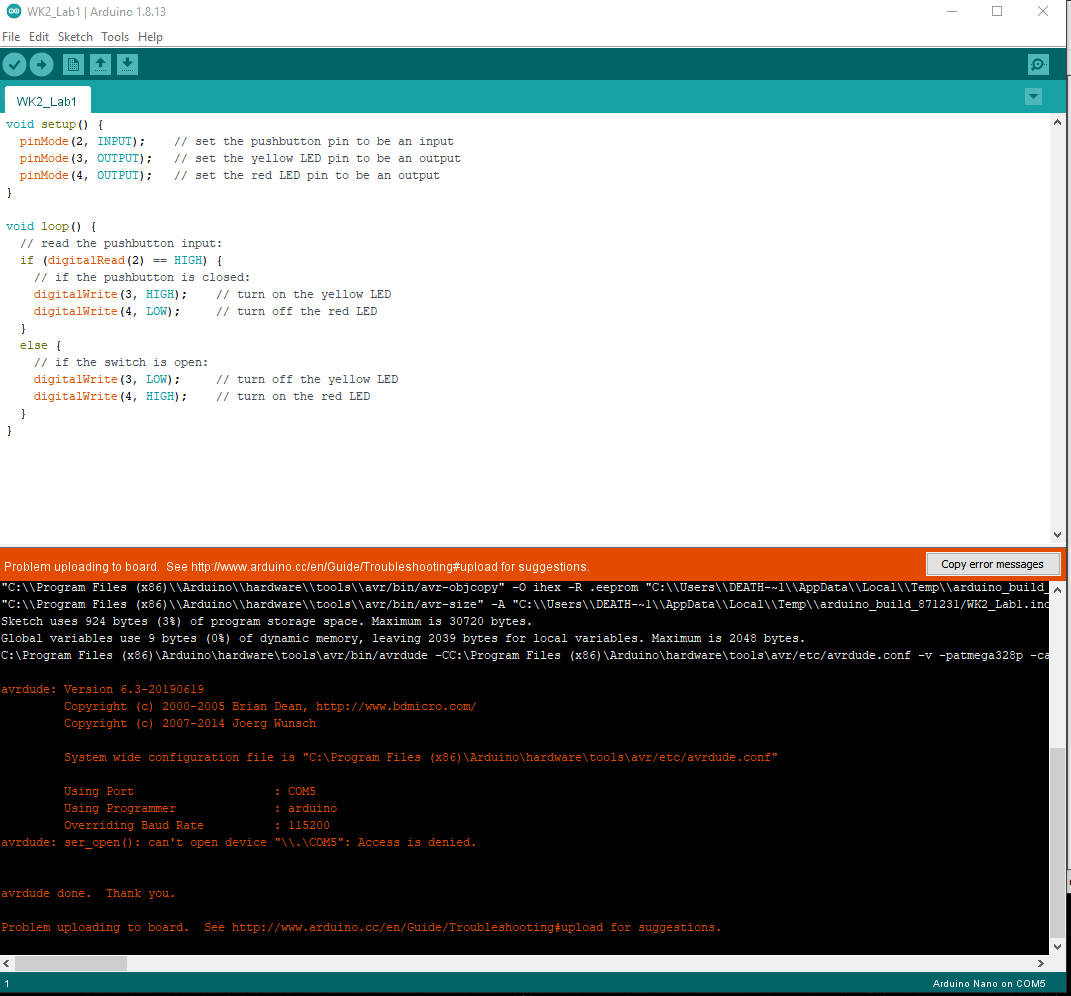
I made a few attempts to upload the sketch with he same result:
avrdude: ser_open(): can’t open device “.COM5”: Access is denied.
I swapped out the Nano 33Iot with another one, same result. I swapped the Nano for an Uno, same result. I then checked to make sure the USB-micro USB cord was able to send/receive data, it was. So at this point I figured it had to be software related, I started with drivers for USB ports, then moved onto checking how the COM ports were assigned, checked to see what programs were holding COM ports open, changed firewall and anti-virus settings. Nothing worked, thought it might be my desktop, switched to my laptop, same behavior.
Now that I was well frazzled it was time to reach out, hoped on discord and asked in anyone else was having the same issue. Luckily Tom Igeo was on and we started to troubleshoot some other ways.

Went through another couple of rounds with drivers and the like, when we finally decided to install an old version of the Arduino IDE, and BAM!! Upload successful.
After a few hours of fuss with the IDE, uploading was a non-issue. I was able to write I bit of code for a pair of force sensitive resistors (FSR) and they work for the most part. I may have used the wrong pulldown resistor, not calculated the remapping of the range correctly, or these FSRs always allow some amount of voltage through, bit thinking about it now, I might be able to adjust the low end of the range to avoid this behavior. I will try this out and put my results in the comments.
const int redLED = 10;     // pin that the red LED is on
const int greenLED = 11;   // pin that the green LED is on
int rightSensorValue = 0;  // value read from the right analog sensor
int leftSensorValue = 0;   // value read from the left analog sensor


void setup() {
  // initialize serial communications at 9600 bps:
  Serial.begin(9600);
  // declare the led pins as outputs:
  pinMode(redLED, OUTPUT);
  pinMode(greenLED, OUTPUT);
}
void loop() {
    rightSensorValue = analogRead(A0); // read the pot value
    // map the sensor value from the input range (400 - 900, for example)
    // to the output range (0-255). Change the values 400 and 900 below
    // to match the range your analog input gives:
    int brightness = rightSensorValue;
    analogWrite(redLED, brightness);  // set the LED brightness with the result
    Serial.println(rightSensorValue);   // print the sensor value back to the serial monitor

    // now do the same for the other sensor and LED:
    leftSensorValue = analogRead(A1); // read the pot value
    // map the sensor value to the brightness again. No need to
    // declare the variable again, since you did so above:
    brightness = leftSensorValue;
    analogWrite(greenLED, brightness);  // set the LED brightness with the result
    Serial.println(leftSensorValue);   // print the sensor value back to the serial monitor
  }


