Take a right at the H-Bridge
Motor control is the topic for this week, specifically DC Nano motors and stepper motors. The biggest take-away from this weeks material is that the inclusion of an H-Bridge is imperative if bi-directional rotation is needed.
This block of code is running on an Arduino Nano 33 IoT and the circuit is using a MOSEFT instead of a transistor. I tried using a different transistor, NPN, 60V 200mA (2N3904), than the on called out in the lab however, I was unable to get a working circuit with it. The specs on the data sheet made me think it would do the job but no such luck. The MOSFET had no issues at all. This circuit also includes the use of a potentiometer in order to control the rotation speed.
const int transistorPin = 9;    // connected to the base of the transistor

 void setup() {
   // set  the transistor pin as output:
   pinMode(transistorPin, OUTPUT);
 }

 void loop() {
   // read the potentiometer:
   int sensorValue = analogRead(A0);
   // map the sensor value to a range from 0 - 255:
   int outputValue = map(sensorValue, 0, 1023, 0, 255);
   // use that to control the transistor:
   analogWrite(transistorPin, outputValue);
 }
Once the circuit with the MOSFET was successful it was time to use an H-Bridge in order to control the direction of the motor. A small slide switch was used in order to select rotation direction. This circuit still includes the use of a potentiometer in order to control speed of rotation. The H-Bridge used here has two motor inputs however, in this example I used only one input.
const int switchPin = 2;    // switch input
const int motor1Pin = 3;    // Motor driver leg 1 (pin 3, AIN1)
const int motor2Pin = 4;    // Motor driver leg 2 (pin 4, AIN2)
const int pwmPin = 9;       // Motor driver PWM pin
int analogValue = 0;
int spd = 0;

void setup() {
  // set the switch as an input:
  pinMode(switchPin, INPUT);

  // set all the other pins you're using as outputs:
  pinMode(motor1Pin, OUTPUT);
  pinMode(motor2Pin, OUTPUT);
  pinMode(pwmPin, OUTPUT);

  // set PWM enable pin high so that motor can turn on:
  digitalWrite(pwmPin, HIGH);
}


void loop() {
  // if the switch is high, motor will turn on one direction:
  if (digitalRead(switchPin) == HIGH) {
    digitalWrite(motor1Pin, LOW);   // set leg 1 of the motor driver low
    //      digitalWrite(motor2Pin, HIGH);  // set leg 2 of the motor driver high
    analogValue = analogRead(A0);
    spd = analogValue / 4;
    analogWrite(motor2Pin, spd);
  }
  // if the switch is low, motor will turn in the other direction:
  else {
    //      digitalWrite(motor1Pin, HIGH);  // set leg 1 of the motor driver high
    digitalWrite(motor2Pin, LOW);   // set leg 2 of the motor driver low
    analogValue = analogRead(A0);
    spd = analogValue / 4;
    analogWrite(motor1Pin, spd);
  }
}
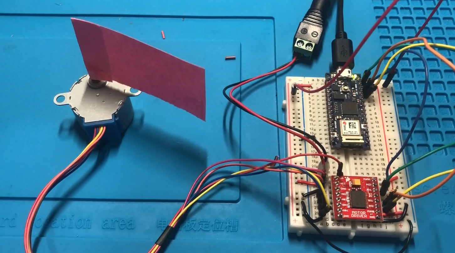
The final item on the agenda of motors and the H-Bridge was to control a stepper motor. Again here we use a Dual TB6612FNG for the H-Bridge and a Small Reduction Stepper Motor – 12VDC 32-Step 1/16 Gearing from Adafruit as the motor. There were tow steps to this lab, I was unable to get the first portion of the lab to work. Here is the code for unsuccessful initialization of the stepper.
#include "Stepper.h"

const int stepsPerRevolution = 513;  // change this to fit the number of steps per revolution
                                     // for your motor

// initialize the stepper library on pins 8 through 11:
//Stepper myStepper(stepsPerRevolution, 8,9,10,11);
Stepper myStepper(stepsPerRevolution, 9,10,11,12);

int stepCount = 0;         // number of steps the motor has taken

void setup() {
  // initialize the serial port:
  Serial.begin(9600);
}

void loop() {
  // step one step:
  myStepper.step(1);
  Serial.print("steps:" );
  Serial.println(stepCount);
  stepCount++;
  delay(500);
}
I believe this is due to the specific stepper I had on hand. After reading the documentation there was a note “you shouldn’t use interleaved or micro-stepping to control” this made me consider moving on to the second half of the lab without success in the first part. This paid off, this block of code was successful on the first try.
#include "Stepper.h"

const int stepsPerRevolution = 513;  // change this to fit the number of steps per revolution
                                     // for your motor

// initialize the stepper library on pins 8 through 11:
Stepper myStepper(stepsPerRevolution, 9,10,11,12);

void setup() {
  // set the speed at 60 rpm:
  myStepper.setSpeed(10);
  // initialize the serial port:
  Serial.begin(9600);
}

void loop() {
  // step one revolution  in one direction:
   Serial.println("clockwise");
  myStepper.step(stepsPerRevolution);
  delay(500);

   // step one revolution in the other direction:
  Serial.println("counterclockwise");
  myStepper.step(-stepsPerRevolution);
  delay(500);
}
I will note that in the first section of this lab with power connected and the circuit triple checked, when holding the stepper the pulse could be felt. This lead me to believe it was power issue however, that was not the case. The specs for this stepper showed it would function with as little as 5V, I used both a 9V battery and a a 12V wall wort with no change in observation.
I see the final project looming in the distance, ideas float in and out, maybe something to do with digital collage I will attempt… just one thought of many.

