Testing, Testing
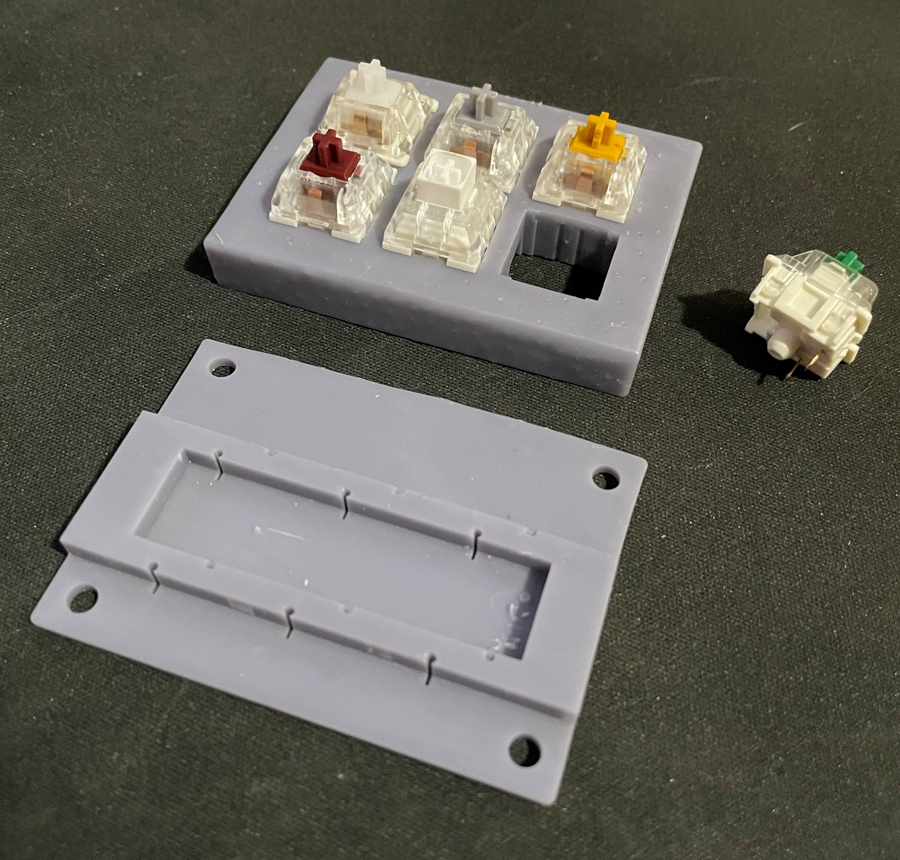
The mid plate of the tester reveals the footprint of the switches, a PCB can replace this layer. In this configuration there is space under this plate to hand wire the components if desired. The final version of this will use a PCB with surface mount components and with the use Holtite inserts, the keyswitches will be hot swappable.
This is the circuit diagram for the PCB. Note the six screw terminals at the right of the schematic, these will allow this board to connect with any microcontroller. This attention to a “universal” connection method was necessary for use with the modular wall, it also allows the user to have this as a standalone macro keyboard,
Take one of the PCB traces. I hate it, I will try again in order to clean up the design and not have to use any through holes and jumper wire. I may move to a double sided PCB for two reasons. The SMD components could bet in the way of the switch footprint and to clean up the traces. As I plotted the traces I asked myself a question about the need for both a diode and and LED to eradicate ghosting. In my head the both function the same way, only letting electricity flow in one direction. I will need some more research to answer this question.


