The PenduLight, a journey form inception to artifact.
The PenduLight, a journey form inception to artifact. For those who have not read my previous posts about design and early fabrication I will post a quick review here.
For the TL;DR scroll top the bottom.
The full text is available below.
The initial idea behind the PenduLight was to capture the movement of a the plumb of the pendulum equipped with an RGB LED allowing the path to be recorded in a long exposer. I wanted to be able to influence the the movements of the plumb to do this I attached the the suspension cable to a lever-arm which in turn was attached to a stepper motor. I used a toggle to change direction and a rotary potentiometer to change the speed.
I think overall the project was a success. There were some issues along the way, most were solved by making small adjustment, however, there are a few changes that I would like to make.
- I need a more powerful motor, I didn’t think about the amount of torque required to change the direction of the motor with the lever-arm attached. I also think a larger diameter spindle would help with some binding problems. The current circuitry will allow me to use a 24V 2A motor without changing anything except for the battery.
- The housing for the motor worked but could have been better, the initial idea to create an 80/20 frame for the PenduLight would be best, it would allow for small adjustments and a very rigid attachment point.
- Use barrel clasp to attach the separate halves of the suspension cable, this would make changing the length or material type a less time consuming change.
- Use a heat insert at the top of the plumb, again this would make installation of the plumb to the suspension cable much easier.
- Use a four strand wire instead of forgetting to buy and then have to construct one hahaha.
I’m sure there are a few other changes I would like to make and there are some new features I would like to incorporate into the overall design as well.
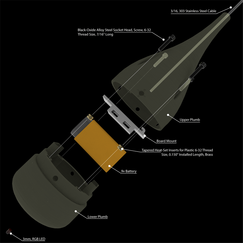
Exploded view of the plumb component of the PenduLight. This part is the most refined but still needs a few touchups. The inclusion of a better method for attaching the the microprocessor and the addition of a heat-insert at the top for suspension cable attachment.

Collapsed plumb component rendering.
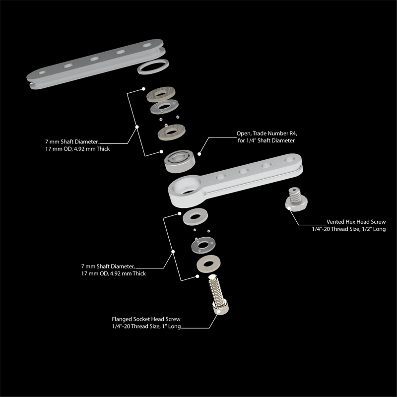
Exploded view of the lever-arm, this part need some refinement. It seems like it would be better to use a disc rather than an arm in this situation. I believe the disc would balance the pressure on the motor spindle reliving some of the binding.

Collapsed view of the lever-arm.

All parts for the pendulum except for the controller.

Photo showing manufacturing error of the lever-arm.
It took a little bit of time to get the code for the stepper to work well. This code was adapted from the moto-knob code available with the Arduino IDE.
/*
  Code adapted from
  MotorKnob
   A stepper motor follows the turns of a potentiometer
   (or other sensor) on analog input 0.
   http://www.arduino.cc/en/Reference/Stepper
   This example code is in the public domain.
*/
#include <Stepper.h>

const int stepsFull = 200;

//Stepper pedulumstepper(stepsFull, 2, 3, 5, 6);
Stepper pedulumstepper(stepsFull, 3, 5, 6, 9);
//int dirControl = 9;
int dirControl = 10;

void setup() {

}
void loop() {
  int sensorReading = analogRead(A0);
  int stepperSpeed = map(sensorReading, 0, 1023, 0, 100);
  if (stepperSpeed > 0) {
    delay(1);
    if (digitalRead(dirControl) == LOW) {
      pedulumstepper.setSpeed(stepperSpeed);
      pedulumstepper.step(stepsFull / 50);
    } else {
      pedulumstepper.setSpeed(stepperSpeed);
      pedulumstepper.step(-stepsFull / 50);
    }
  }
}
To cycle the RGB LED the code wasn’t that bad, I adapted it from James Harton, and can be found here https://gist.github.com/jimsynz/766994
const int redPin = 3;
const int greenPin = 5;
const int bluePin = 6;

void setup() {
  // Start off with the LED off.
  setColourRgb(0,0,0);
}

void loop() {
  unsigned int rgbColour[3];

  // Start off with red.
  rgbColour[0] = 255;
  rgbColour[1] = 0;
  rgbColour[2] = 0;

  // Choose the colours to increment and decrement.
  for (int decColour = 0; decColour < 3; decColour += 1) {
    int incColour = decColour == 2 ? 0 : decColour + 1;

    // cross-fade the two colours.
    for(int i = 0; i < 255; i += 1) {
      rgbColour[decColour] -= 1;
      rgbColour[incColour] += 1;

 //quick and ugly invert
//      setColourRgb(255-rgbColour[0], 255-rgbColour[1], 255-rgbColour[2]);
      setColourRgb(rgbColour[0], rgbColour[1], rgbColour[2]);
      delay(50);
    }
  }
}

void setColourRgb(unsigned int red, unsigned int green, unsigned int blue) {
  analogWrite(redPin, red);
  analogWrite(greenPin, green);
  analogWrite(bluePin, blue);
 }
I used a Two different boards in the construction of the PenduLight. Originally I was going to use two Arduino Nano Every which is a very cost effective board and has just enough digital pins to accomplish the tasks at hand. I ended up using one Nano Every and one Nano 33 IoT.
I used the Nano 33 IoT with the stepper. I had some issues with the motor driver. I started with a SparkFun dual H-bridge that used a TB6612FNG, it was being very sporadic in the operation of the stepper. I read in the data sheet that it doesn’t handle low-voltage steppers very well. So I ordered a Pololu DRV8834 low-voltage stepper motor driver. This board has the advantage of a small potentiometer that allows you to set a current limit. HOWEVER after a full day of troubleshooting the code and wiring I abandoned the board and went back to the TB6612FNG and to my surprise it worked flawlessly. I still don’t know why it worked out the way it did, I would like to do more research into why.
I decided to use a proto-board and solder everything to reduce the since of the controller box. This is where I ended up change from the original Nano Every to the Nano 33 IoT. In the end I didn’t actually have to do this. After I finished soldering to the proto-board nothing worked, I checked my wiring but didn’t see anything wrong. So I pulled the Nano Every off, which was a royal pain. I connected it to the USB and it worked. I was stumped. So I switched to the Nano 33 IoT, soldered it up and… it didn’t work! I knew at this point it had to be a wiring issue. I checked for solder bridges or crossed wires and finally found the culprit. The VCC in was attached to ground, Had I spent a few extra minutes checking the wiring first I wouldn’t have had pull the Nano Every off, we live, we learn.

This is the CRV8834 which I did not end up using, notice the small silver disk towards the lower left of the white board, that is the current limiting potentiometer.

Proto-board with all components soldered in place and working, hahah

Controller box with all components installed.

The RGB LED was much simpler on the wiring side. I used the Nano Every and a diffuse cathode RGB LED.
I used 9V batteries for both the LED and the motor. In hindsight and after doing some more calculations the 9V choice for the motor isn’t the best option. In the future I will use a different motor with more torque which will need a different battery.

Board installed on the carrier.

Heat setting the threaded inserts.

All components installed into the lower half of the plumb.


Completed plumb.

All components ready to hang.

Setup in the door lights on.

In the door backlit.

Just the RGB LED on (don’t mind the power strip light in the back).
Process Gallery


AND NOW FOR THE ARTIFACT, THE REASON ALL OF THIS EFFORT AND DESIGN HAPPEND IN THE FIRST PLACE.


