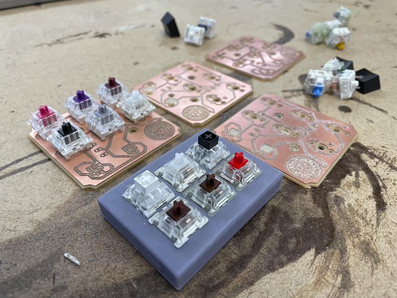
Is it time to make a PCB yet?
The short answer is yes. The board design has been finalized and tested by milling a PCB using the other mill. Both rubber dome pad interlaces needed to be designed and validated. We we able to do that using the cut PCB. We will use JLCpcb to produce the PCBs so we can assure that they work hahaha.
Example code for a 3 x 3 matrix.
#include <Keypad.h>

const byte ROWS = 3;
const byte COLS = 3;

char nonaGrid[ROWS][COLS] = {
  {'1', '2', '3'},
  {'4', '5', '6'},
  {'7', '8', '9'}
  };

byte rowPins[ROWS] = {9, 8, 7};
byte colPins[COLS] = {5, 4, 3};

Keypad keyTester = Keypad(makeKeymap(nonaGrid), rowPins, colPins, ROWS, COLS);

void setup(){
  Serial.begin(9600);
}

void loop(){
  char keyTester = keyTester.getKey();

  if (customKey){
    Serial.println(customKey);
  }
}


