3 Step Switch

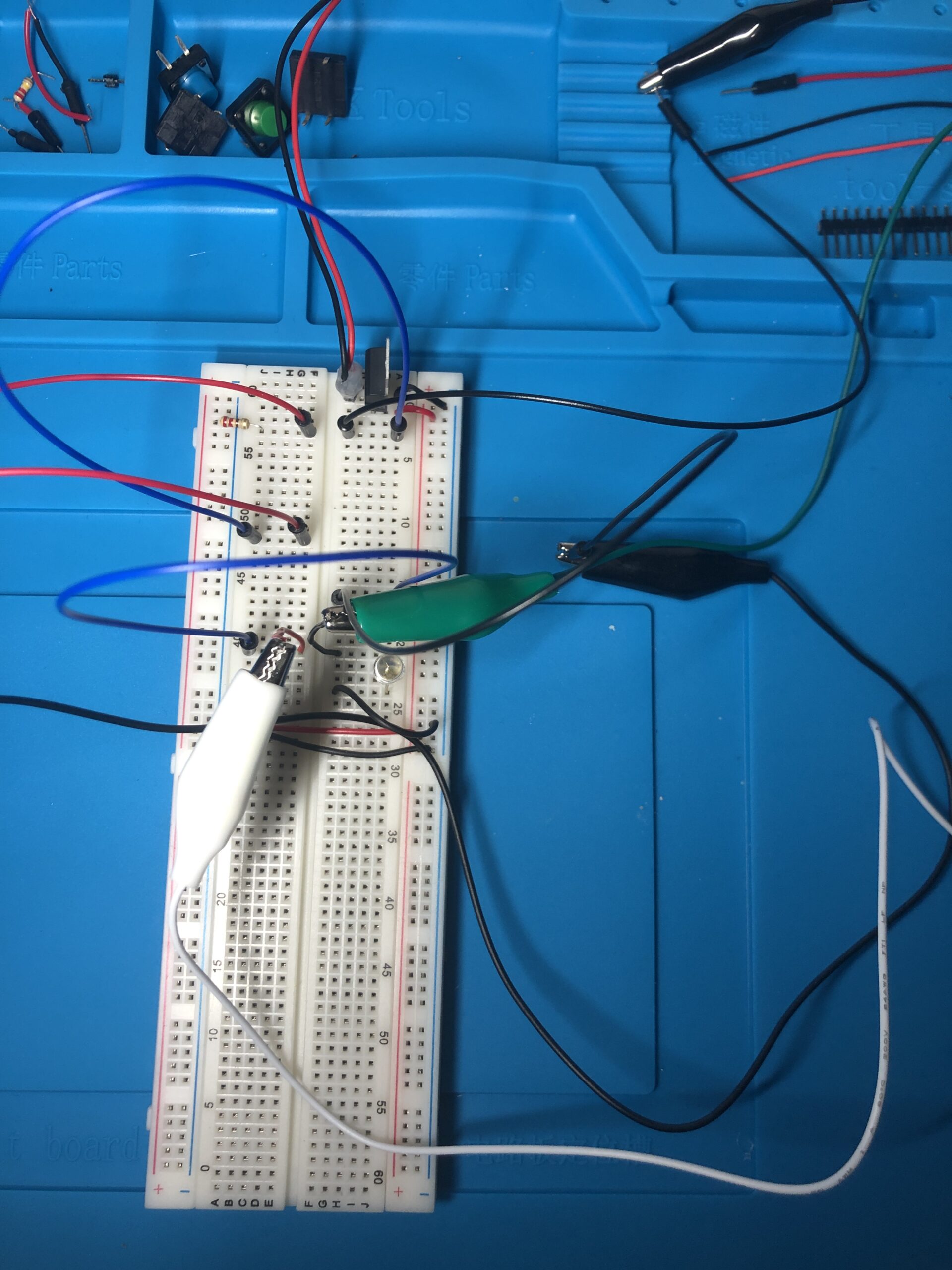
At left is a diagram of the final 3 Step Switch. The main actions used to create this switch were opening a drawer, extending a desk lamp, and placing a cup on a coaster. But first lets talk about getting to the point where I could think of how to make this work. The exercises outline in the syllabus were very clear and gave a good foundation about how the flow of electricity moves along a circuit. Understanding the breadboard and how it is constructed was a critical step in this process. After reading through the material I experimented with different configurations on the breadboard. One thing I noticed was how dim the output of the LED was, I originally used a 220k ohm resistor which made it very dim. I then removed the resistor completely, bingo!! Bright light, only problem was this allowed too much current for the LED and bam! I burnt a few up doing this. I did some measuring with the multimeter and confirmed the current was too great for the LED and decided on using a 220 ohm resistor. This gave me the desired light output from the LED and did not harm the LED. I made a DC plug with header pins for use with the breadboard and covered any exposed wires with hot glue to ensure this adapter did not short out. I took this idea from one of the videos staring Tom Igoe.

The video shows one step one of the switch, the desk lamp is raised into working position. Two wires run up the back of the lamp and a patch of copper tape was applied to the top of the lamp arm. When the lamp arm is raised the wires contact the copper tape and complete the switch.

The next component is the drawer switch. When the drawer is opened the switch is closed completing the circuit. Again I used copper tape and wire to complete the switch, the copper take is placed along the top edge of the drawer leaving a gap of 1 inch at the front. This allows one wire to rest off the tape when the drawer is closed. When the drawer is opened the front wire to contact the copper tape and complete the circuit.

The next and final component is a pressure switch that is activated by placing a cup on a coaster. This video contains all three elements in the switch wired in a series so that all actions must be completed for the LED to light. For the most part this was a fairly simple project, the hardest parts was extrapolating out how the momentary push-button switch worked in terms of the current flow. (The video containing the success with the momentary switch is below.) After figuring this out it was just a batter of running the wires and assembling the final configuration.

Here you will find an assortment of images related to how I created this 3 Step Switch. Please comment and question.

3 Step Switch
3 Step Switch
3 Step Switch
3 Step Switch
3 Step Switch
3 Step Switch