Dear reader, if you have been paying attention and have a good memory you will recall the PenduLight system
Dear reader, if you have been paying attention and have a good memory you will recall the PenduLight system was based on a single point of rotation via a motor. That point of rotation was connected to a a compound lever resulting in a varied attachment point for the pendulum. This was a good start, however, the output was mostly circular with some small anomalies in path. Interesting outcomes but they could be more interesting still. Enter the use of an X/Y gantry otherwise known as a cartesian robot. The use of the X/Y gantry will allow for many more variations in path.
Each axis of the X/Y gantry will have 2 variables to feed data into, the travel distance and the speed of travel. Both variables will be collected form sensors in the room/installation. The data to be collect has not been decided upon but some options are number of people entering and exiting the room, ambient volume, and more than likely there will be a random element to one variable on each axis.
Below you will find a a visualization of the reasinging behind switching form the “single point of rotation via a motor system” to the X/Y gantry.
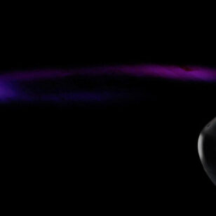
After deciding to change from the stationary single rotation point to the X/Y gantry system of attaching the pendulum, I wanted to see if my theory about the outputs was correct. I held the pendulum attachment point above the camera and moved it randomly inside an 8in x 8in square bounding box and recorded the movements. As expected there was more varied output. Which is what I was aiming for, this little exercise also showed me that quick change movements did not have as much impact with the final output. I will be able to use this information to aid in how the gantry should move to produce the most varied outputs. Once I have the sensors controlling the movement, I will begin to change the speed, distance, and timing of the system.


